-
×
 Heart Rate Monitor Kit with AD8232 ECG sensor module
1 × ₹425.00
Heart Rate Monitor Kit with AD8232 ECG sensor module
1 × ₹425.00 -
×
 ESP8266 NodeMCU CP2102 Board
1 × ₹245.00
ESP8266 NodeMCU CP2102 Board
1 × ₹245.00 -
×
 Neo-6m GPS Module Flight Controller Module 3V-5V with Super Strong Ceramic Antenna for Arduino EEPROM APM 2.5 AB0156
1 × ₹260.00
Neo-6m GPS Module Flight Controller Module 3V-5V with Super Strong Ceramic Antenna for Arduino EEPROM APM 2.5 AB0156
1 × ₹260.00 -
×
 Ds18B20 Waterproof Temperature Probe – Black (1 meter)
1 × ₹90.00
Ds18B20 Waterproof Temperature Probe – Black (1 meter)
1 × ₹90.00 -
×
 ESP32 (38 Pin) WiFi + Bluetooth NodeMCU-32 Development Board AB0271
1 × ₹325.00
ESP32 (38 Pin) WiFi + Bluetooth NodeMCU-32 Development Board AB0271
1 × ₹325.00 -
×
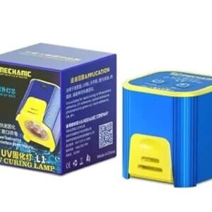 Mechanic L1 Uv Curing Lamp For Phone PCB UV Glue Curing Repair, Power: Type-c Charging Cable AB0243
1 × ₹1,050.00
Mechanic L1 Uv Curing Lamp For Phone PCB UV Glue Curing Repair, Power: Type-c Charging Cable AB0243
1 × ₹1,050.00 -
×
 LM2596 DC-DC Buck Converter Step Down Module
1 × ₹45.00
LM2596 DC-DC Buck Converter Step Down Module
1 × ₹45.00 -
×
 Cube Aerosol Multi Purpose Spray Paint Gray Color 400 ml Pack of 1 (Gray)
1 × ₹110.00
Cube Aerosol Multi Purpose Spray Paint Gray Color 400 ml Pack of 1 (Gray)
1 × ₹110.00 -
×
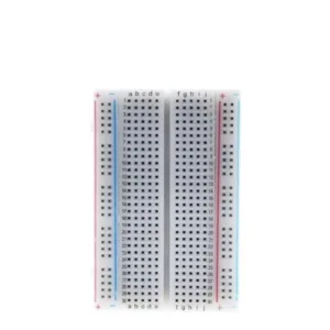 400 Point Solderless Breadboard AB0208
1 × ₹45.00
400 Point Solderless Breadboard AB0208
1 × ₹45.00
Subtotal: ₹2,595.00